Part B – FET Open
Short Proposals: Project description
B1. Title page
Proposal
full title: OMNIVIEWS "Omni-directional Visual
System"
Proposal
acronym: OMNIVIEWS
Date
of preparation: 14 May 2000
Proposal
number: -
B2. Project
description
The present project is based on two innovative optical and microelectronic technologies that have never before been used together. The long-term objective is to realize a digital video camera providing immediately usable omni-directional images (i.e. images with a field of view of 360°) and demonstrating its utility in application areas such as remote surveillance and visually guided navigation. The present proposal is in the form of an assessment project with the aim of demonstrating the feasibility of underlying technologies as well as the advantages of their integration. More specifically we intend to demonstrate that the long term objective can be reached by using two complementary technologies namely an omni-directional optical mirror and a matching microelectronic CMOS visual sensor. The advantage will be that the topological distortions introduced by the mirror will be corrected by the geometry of the sensor array at no computational cost. The final device will be in the form of a microcamera with a digital output whose images will be immediately useable by human observers and/or further processed by a computer.
Objective
The goal of the project is to integrate optical, optoelectronic, hardware, and software technology to realise a smart visual sensor, and to demonstrate its utility in key application areas. In particular our intention is to design and realise a low-cost, miniaturised digital camera acquiring panoramic (360 deg) images and performing a useful low-level processing on the incoming stream of images in real-time. Target applications include surveillance, quality control and mobile robot and vehicle navigation.
Technologies
The classical acquisition of panoramic
images is based on the use of mechanical or optical devices. The mechanical solutions are based on
motorised linear or array-based cameras, usually with a 360 deg rotation,
scanning the visual world. The main advantage of the mechanical solution is the
possibility of acquiring very high-resolution images and its major drawback the
time required to mechanically scan the scene to obtain a single image. Optical solutions provide lower
resolution images but are the most appropriate for real-time applications.
 Two optical alternatives
have been proposed, namely the use of mirrors and the use of special purpose
lenses (such as fish eye lenses). As we
intend to investigate real-time processing and applications, only the optical
approach will be pursued. Moreover, because of past experience of a member of
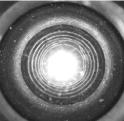
the consortium, the preferred solution is the use of optical mirrors. The
set-up and an example image using this solution are shown in Figs. 1a and 1b,
respectively. As it can be seen the image is not immediately understandable
because of the geometric distortion introduced by the mirror to obtain a
panoramic view. Two different transforms are perceptually meaningful at this
place. The first transform maps the original panoramic image onto a cylinder
and the second maps the cylinder into a plane thus providing a complete
panoramic image as shown in Fig. 2. The advantage of such a mapping lays in
providing the observer with a complete view of its surrounding in one image
which can be refreshed at video rate.
Two optical alternatives
have been proposed, namely the use of mirrors and the use of special purpose
lenses (such as fish eye lenses). As we
intend to investigate real-time processing and applications, only the optical
approach will be pursued. Moreover, because of past experience of a member of
the consortium, the preferred solution is the use of optical mirrors. The
set-up and an example image using this solution are shown in Figs. 1a and 1b,
respectively. As it can be seen the image is not immediately understandable
because of the geometric distortion introduced by the mirror to obtain a
panoramic view. Two different transforms are perceptually meaningful at this
place. The first transform maps the original panoramic image onto a cylinder
and the second maps the cylinder into a plane thus providing a complete
panoramic image as shown in Fig. 2. The advantage of such a mapping lays in
providing the observer with a complete view of its surrounding in one image
which can be refreshed at video rate.
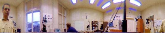
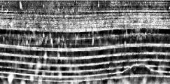
Figure 2: Example panoramic image
The second transform cuts out only a part of the panoramic view and re-maps it into a virtual perspective image. Therefore, the resulting image looks like an image taken by an ordinary camera as shown in Fig. 3c, extracted from the panoramic image in Figure 3b.
 Figure 3: (a) A spherical
mirror profile (b) the corresponding panoramic image and (c) an extracted view.
Figure 3: (a) A spherical
mirror profile (b) the corresponding panoramic image and (c) an extracted view.
The advantage is that e.g. more users can simultaneously see and rotate their virtual view at the same time without moving any component on the camera. It may be advantageous when more than one user wants to look onto different directions using the same camera. It is a kind of virtual multi-user pan and tilt camera.
Let us stress that true perspective images (for measurement etc.) can only be obtained with a perspective camera, which has an effective centre of projection. It has been shown that such a projection can be obtained using a hyperbolic or a parabolic mirror in combination with pinhole cameras. However, as shown at Fig. 3 images are visually almost correct even with different mirror shapes such as a spherical one.
 One goal of the project will
be to use a CMOS visual sensor with a geometry matching the profile of the
mirror so that the images will be directly understandable to human operators.
The kind of sensor geometry we intend to use is, therefore, space-variant (i.e.
with variable resolution), and with a polar structure. One such geometry is,
for example, the so-called log-polar (or retina-like) geometry shown in Fig. 4.
With respect to the present project, the matching between the optical device
and the visual sensor of Fig. 4 can be better understood considering two
aspects. Firstly the size of the photosites increases linearly with
eccentricity and secondly the photosites are arranged over concentric rings
with each ring composed by an equal number of pixels. The read-
One goal of the project will
be to use a CMOS visual sensor with a geometry matching the profile of the
mirror so that the images will be directly understandable to human operators.
The kind of sensor geometry we intend to use is, therefore, space-variant (i.e.
with variable resolution), and with a polar structure. One such geometry is,
for example, the so-called log-polar (or retina-like) geometry shown in Fig. 4.
With respect to the present project, the matching between the optical device
and the visual sensor of Fig. 4 can be better understood considering two
aspects. Firstly the size of the photosites increases linearly with
eccentricity and secondly the photosites are arranged over concentric rings
with each ring composed by an equal number of pixels. The read- out of the sensor array is performed so that a point of the polar
structure at coordinates (ρ,θ) is mapped into Cartesian plane at coordinates (logρ, θ). An
example of such a mapping is shown in Fig. 5. It should be intuitively clear
that, if the structure of the sensor is matched to the curvature of the mirror,
the images acquired by the device (mirror + retina-like camera) are immediately
in a panoramic form. In other words the images will be directly in the form of
Fig. 2 and not as shown in Fig. 1a. Secondly, the increase of resolution in the
sensor array can be designed so that the resulting panoramic image is
out of the sensor array is performed so that a point of the polar
structure at coordinates (ρ,θ) is mapped into Cartesian plane at coordinates (logρ, θ). An
example of such a mapping is shown in Fig. 5. It should be intuitively clear
that, if the structure of the sensor is matched to the curvature of the mirror,
the images acquired by the device (mirror + retina-like camera) are immediately
in a panoramic form. In other words the images will be directly in the form of
Fig. 2 and not as shown in Fig. 1a. Secondly, the increase of resolution in the
sensor array can be designed so that the resulting panoramic image is  constant resolution
eliminating the in-homogeneity seen in Fig. 2 (compare the upper and the lower
part of the picture). A partner of this proposal has extensive experience with
the design and use of space-variant sensors (Fig. 6). As one of the objectives of the project is to provide an
integrated device for real time operation, we also intend to investigate the
hardware implementation of low-level, computational intensive operators,
matched to the optical and electronic geometry. In particular, what we intend
to study is the hardware implementation of motion detection and estimation
operators. It is well known that the implementation in hardware of linear
algorithms is straightforward and moreover, it leads to more compact and testable
devices. The choose of the mirror profile, so that it will fit the sensors
geometry, is expected to provide linear algorithms for the images elaboration,
which can be transferred into hardware very easily.
constant resolution
eliminating the in-homogeneity seen in Fig. 2 (compare the upper and the lower
part of the picture). A partner of this proposal has extensive experience with
the design and use of space-variant sensors (Fig. 6). As one of the objectives of the project is to provide an
integrated device for real time operation, we also intend to investigate the
hardware implementation of low-level, computational intensive operators,
matched to the optical and electronic geometry. In particular, what we intend
to study is the hardware implementation of motion detection and estimation
operators. It is well known that the implementation in hardware of linear
algorithms is straightforward and moreover, it leads to more compact and testable
devices. The choose of the mirror profile, so that it will fit the sensors
geometry, is expected to provide linear algorithms for the images elaboration,
which can be transferred into hardware very easily.
Project Phases
From the technological perspective our final goal is to realise a miniature device including mirror, visual sensor and hardware pre-processors and to show its advantages in the targeted application areas. This goal will be achieved in two phases. The first through the present "assessment" project and the second, subjected to the result of the first phase, as a full fledged R&D project.
First Phase
At the first step, which is the objective of the present proposal, an assessment project is requested. This phase is aimed at demonstrating the feasibility of the approach by realising an omni-directional visual camera based on the optical and electronic sensors already available. During this first phase no new major component will be realised but the matching of the optical and microelectronic technologies will be assessed and demonstrated.
One of the crucial aspects of this proposal is to define the best match between the profile of the mirror and the distribution of the sensitive elements of the CMOS sensor. Another crucial aspect is the study and definition of the best match between image geometry resulting from the mirror/sensor coupling, and the visual measures required. For example, starting from a log-polar sensor, the optimal profile may be a conic mirror because, a proper match between the rate-of-increase of the log-polar geometry and the angle of the cone, will produce panoramic images so that: a) their elaboration will demand less effort and, therefore, simpler and faster hardware structures and b) their geometry will be directly usable by a human operator. On the other hand, conic mirrors seem not optimal for some classes of visual processing (e.g. stereo matching). Aspects of this kind need to be properly addressed taking into consideration technological, processing and application-derived constraints.
At the end of this first phase the aim is to obtain the following information:
- Definition of the optimal profile of the mirror
- Definition of the matching distribution of the sensing elements in the visual sensor
- Selection of processing primitives to be realised in hardware
- Estimate of the size of device and the speed of operation
- Preliminary demonstration of a potential application
Second Phase
According to the results of the first assessment phase, the following technological developments may be required:
- Design and fabrication of a new mirror
- Design and fabrication of a new CMOS sensor
- Design and fabrication of a compact hardware device (Gate Array or ASIC)
- Demonstration
It is worth stressing that not all the new design may be required and that, according to the actual plan defined at the end of the first phase, one or two technological partners (namely industries) may be required to provide the consortium with specific expertises. To be prepared for a smooth transition, a proper amount of funding is reserved during the first phase, to allow future potential partners in participating on the decision making and testing processes.
Applications
Broadly speaking, the use of panoramic cameras has significant application potentials in areas such as surveillance, quality control and mobile robot navigation. Regarding the surveillance, a complete field of view will allow to cover a much larger area using fewer cameras compared to ordinary cameras. Similarly, person/vehicle tracking will be possible in all directions without moving the camera therefore reducing reaction time and costs as well as increasing the reliability of the surveillance system. The lower resolution of panoramic sensors suits well to a real time object detection and tracking. In order to gain a high-resolution image, the panoramic camera can be coupled with a pan and tilt camera controlled by the output from the panoramic camera in order to keep the object of interest inside its view. For reliable tracking, it is vital to assure evenly distributed resolution across the panoramic image. This is one of the goals of the first phase of the project.
Quality checking/control of narrow cavities like the inside part of tubes, seals, or drilled holes needs specialised industrial endoscopes having optics similar to a panoramic camera (see Fig. 7 for an example of production quality checking using a panoramic camera). By matching the optics of endoscopes with the pixel layout of the CMOS chip will reduce acquisition time of the images and, thus, significantly decreasing the control cycle time.
(a) (b) (c)
Fig. 7: Images of inspection of a rubber seal using a panoramic camera: (a) the seal with a diameter of appx. 1cm, (b) its view onto the mirror and (c) the warped image
Taking inspiration from nature, it seems easier and more reliable to localise and navigate a mobile robot from the images obtained with a large angle of view than from the images taken by a camera with narrow field of view. One of the main advantages is that the observer sees almost all its environment as it moves and therefore does not loose track of visual landmarks required to estimate its position over time.
 Mounting an omnidirectional
vision sensor on top of a mobile vehicle provides a (distorted) view of the
ground plane and surrounding environment and landmarks. The navigation problems
would be much simplified if a corrected (perspective) view could be determined,
thus providing a scaled orthographic image of the ground plane, that we call bird’s
eye view.
Mounting an omnidirectional
vision sensor on top of a mobile vehicle provides a (distorted) view of the
ground plane and surrounding environment and landmarks. The navigation problems
would be much simplified if a corrected (perspective) view could be determined,
thus providing a scaled orthographic image of the ground plane, that we call bird’s
eye view.
 The side pictures show an
omnidirectional image obtained by a robot travelling along a corridor and the corresponding bird’s eye view. Such images were obtained by using algorithms that
invert the distortion introduced by the omnidirectional camera and could be
directly implemented in hardware and/or by choosing an appropriate combination
of the mirror shape/sensor resolution.
The side pictures show an
omnidirectional image obtained by a robot travelling along a corridor and the corresponding bird’s eye view. Such images were obtained by using algorithms that
invert the distortion introduced by the omnidirectional camera and could be
directly implemented in hardware and/or by choosing an appropriate combination
of the mirror shape/sensor resolution.
Another important advantage of using omnidirectional images from e.g. image flow is much better conditioned if the observer is able to see almost all its surrounding, as features from all sides around him can be used. One of the partners has experience in ego-motion estimation with normal or log-polar images. Additionally, experiments have been done using an artificial compound eye, similar to those found in several insect species. Such eye geometry combines both omnidirectional vision and space-variant pixel distributions. The ego-motion is computed in parallel by analogue filters similar to the Elementary Motion Detectors (EMDs) found in many insect eyes. An image of the compound eye is shown in Figure 9.
Impact of the project
The main impact of the project consists in providing a novel image acquisition combined with a smart image processing allowing achieving a cheap and flexible means of the acquisition of almost complete environment of the observer. Such a technology, when properly implemented, can reduce the costs, bring a new functionality, and simplify visual surveillance as well as contribute to a more reliable usage of vision in the mobile vehicle navigation. In addition to completely new directions that can be opened through the developing of a compact panoramic sensor, the knowledge gained during the sensor construction can directly contribute to a number of practical tasks in near future. A processing of special images as well as the construction of precise industrial endoscopes used for the measurement of dimensions and production quality control will gain directly from studying a wide-angle image formation.
A note on phase-2 of the project
If the first phase of the project will be successful, and with the obvious uncertainties related to advanced technological projects, we anticipate that the proposal for the second phase will have the following structure and duration. The consortium will be extended to include a few industries manufacturing optical and electronic devices as well as a major user for the targeted application field. The role of the technological partners will be that of guiding the academic partners toward the realization of a sound industrial product with strong commercial potential. The duration of the project will be no more than 1.5 years (possibly less), the main constraints being the time required to design and fabricate a new sensor, a new mirror and the accompanying hardware and software. A rough estimate of the financial support required will be of the order of 500 KEuro.