The Database
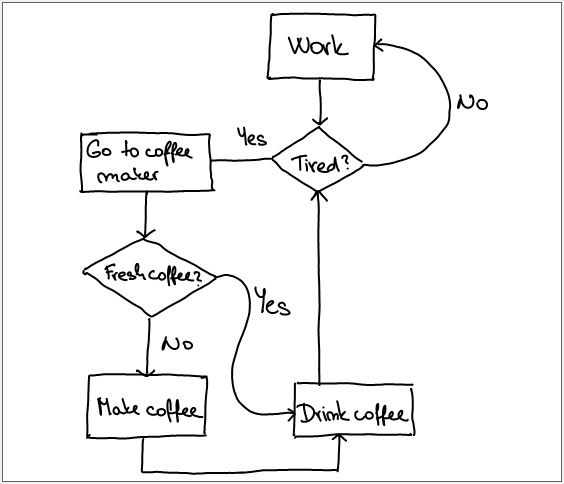
 This is a database of off-line sketched diagrams from the flowchart domain. It was created as an extension to the existing on-line database and it consists of two parts: A) contains images with noise-free 1-pixel wide rasterization of strokes (skeleton images), B) contains scans of a printed thicker stroke visualization containing real noise. We defined a mapping between the dynamic strokes and the static images. The purpose of the database is to provide a benchmark to algorithms for off-line diagram recognition and strokes reconstruction. Having these two databases allows to investigate the impact of the skeletonization algorithm on the recognition results.
Database creation
A)
The page A4 has a printable surface 247 × 170 mm, landscape. We used a canvas 2 918 × 2 008 pixels to obtain 300 dpi when the image is printed. We left 10 pixels on each side for margins. We scaled the strokes to fit the canvas and centered them. The strokes were reasterized in the image using the Bresenham's algorithm. Additionally, we created markers 5 pixels from the top-left and bottom-right corner of the bounding box of the strokes. The markers might be used to find a mapping of the original strokes onto the image. Since the data is noise-free, the mapping is perfect.
B)
We used WeInspire sketching application to visualize the strokes and saved them into PDF files. The canvas in the application is 1 596 × 922 pixels. We scaled and centered the strokes to fit inside as above. Additionally, we drew a bounding rectangle 15 pixel far from the bounding box of the strokes. We printed and then scanned the diagrams to obtain images with natural noise, which do not significantly differ from scans of diagrams drawn using a standard pen and paper. We used All-in-One KONICA MINOLTA bizhub C3110 device and Color Copy 120 g / m2 paper. We used the bounding rectangle to estimate the global transformation mapping the original strokes onto the image. Although we used thicker paper and scanned the diagrams one by one, there might occasionally appear some local misplacements in the mapping (up to 5 pixels) caused by curling paper. It is possible to employ some local fitting transformation if needed.
Download
The database is divided into the two parts described above and the parts are stored in corresponding folders DA and DB. Each part contains the following sub-folders where filenames correspond to the InkML files with the on-line counterpart:
- images contains PNG files with the raterized/scanned images.
- annotation contains XML files with off-line annotation described later.
- strokes contains InkML files reconstructed strokes using our algorithm.
- registration contains PNG files with the online strokes and annotation mapped into the scanned images. It works as verification of the provided mapping transformation. (not part of DA)
The database is free to download.
file: FC_database_offline_1.0.zip
Parsing the Off-line Annotation
The off-line annotation is stored in XML format and thus it should be easy to parse. Here we provide a brief description. The annotation is very similar to the on-line annotation. However, it is based on bounding boxes instead of strokes. Notice that the off-line annotation can be obtained from the on-line annotation using the provided mapping transformation.
The registration header contains all information necessary to create the transformation mapping on-line strokes onto off-line images. It allows to register the two modalities.
There are two markers in case of DA (top-left and bottom-right corner) and four markers in case of DB (all corners of the bounding frame). The distance of the markers from the diagram bounding box in pixels is stored in the tag <frameOffset>. We used the marker points to find the transformation, which is given by the scale, translation and rotation. See the XML template:
			<registration>

				  <markers>

				        <point x="[x_coord]" y="[y_coord]" />

				        <point x="[x_coord]" y="[y_coord]" />

				        <point x="[x_coord]" y="[y_coord]" />

				        <point x="[x_coord]" y="[y_coord]" />

				  </markers>

				  <frameOffset>[distance_from_diagram_BB]</frameOffset>

				  <scale>[scale]</scale>

				  <translation>[t_x] [t_y]</translation>

				  <rotation>[angle] [center_x] [center_y]</rotation>

			</registration>
Symbols are annotated in the following way. Let us note that the tag textMeaning is defined for text only and the tag arrowAnnotation are defined for arrows only.
The arrow annotation contains annotation of the arrow head (its bounding box) and arrow endpoints where the arrow is coming from and going to.
			<symbol id="[id]" name="[symbol_name]">

			      <bounds x="[x_coord]" y="[y_coord]" width="[width]" height="[height]" />

			      <textMeaning>[text]</textMeaning>

			      <arrowAnnotation>

				        <headBounds x="[x_coord]" y="[y_coord]" width="[width]" height="[height]" />

				        <from x="[x_coord]" y="[y_coord]" />

				        <to x="[x_coord]" y="[y_coord]" />

			      </arrowAnnotation>

			</symbol>
Relations are annotated the same way as in the on-line counterpart. Relations are binary (text labeling a symbol) or ternary (arrow connecting two symbols). In the case the relation is binary the third reference to a symbol is not defined and the first reference is always text. In the case of ternary relation the first reference is the arrow, second reference is a symbol where is the arrow coming out and the second reference is the symbol the arrow is coming in.
			<symbolGroup id="[id]" arity="[arity_num]" name="[relation_name]">

			    <symbolView symbolDataRef="[symbol_1_id]" />

			    <symbolView symbolDataRef="[symbol_2_id]" />

			    <symbolView symbolDataRef="[symbol_3_id]" />

			</symbolGroup>
References
If you need to refer to the database, please, us the following paper:
| [1] | Bresler M., Průša D., Hlaváč V.: Recognizing Off-line Flowcharts by Reconstructing Strokes and Using On-line Recognition Techniques. Yet unpublished manuscript. |