Ladies and gentlemen, let me introduce myself. My name is Pavel Pisa. I am a postgraduate student at the Department of Control Engineering, Faculty of Electrical Engineering, CTU Prague. Our group is interested in development of control devices.
This presentation is intended to review principles of combustion engine operation, to show some of the basic problems in combustion engine control, to present some possible ways in on-road measurement on an engine and to outline possible ways to improve and automate engine adjustment procedure.
The internal combustion engine is a thermodynamic apparatus, which converts chemical energy contained in liquid or gas fuel into mechanical energy. Gained energy and power are often represented by a torque and rotation of an output shaft. A main goal of every combustion engine development and control strategy design is to fulfill requested criteria and optimize efficiency of energy conversion. The initial design restrictions are demanded engine horsepower, given dimensions, weight, fuel type, maximal concentration of toxic exhaust gases, etc.

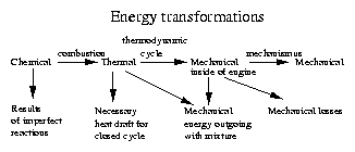
As for the efficiency ratio, it depends on losses in energy transformation. Basic flow of energy transformations and sources of losses can be seen in Figure 1. Losses can be divided into the following categories:
The working cycle of piston internal-combustion engines consists of more actions. First, the volume of the cylinder above the piston is filled by prepared mixture of fuel and air or only by air for engines with in-cylinder mixture preparation. Next action starts, after the intake valve is closed. Enclosed volume is compressed by the piston, which leads to the increasing of pressure and temperature. For engines with internal mixture preparation, fuel is also added during this time period. Then fuel mixture is flamed up by electrical discharge or by self-inflammation. Pressure and temperature are increasing during the time of fuel burning. In-cylinder pressure pushes on the piston head and piston moves down. Mixture is filling the increasing volume. This action is called expansion and the depression of the piston delivers mechanical energy to the engine output and mixture is cooled. The working cycle is completed by the opening of the exhaust valve and cylinder volume is emptied.
One of the surprising facts is, that the amount of energy gained in one piston stroke is in magnitude lower than kinetic energy stored in rotating and moving parts of the engine. Gained energy is even less than energy stored and returned by compression and decompression of in-cylinder contents.
The most important part for thermodynamic description is a high-pressure period of the working cycle. The period starts after the closing of the intake valve and ends by the opening of the exhaust valve. This period is characterized as a process with constant amount of atoms participating in initial and product compounds. Energy is exchanged with ambient only in the form of mechanical work and heat flow between the working medium and cylinder wall.
Fundamental thermodynamic equations describing the thermodynamic cycle are brought in this paragraph. Variables, symbols and measurement units needed for this description are shown in Table 1.
| Variable | Symbol | Unit |
| Pressure | p | Pa |
| Partial Pressure of Compound x | px | Pa |
| Volume | V | m3 , also cm3 |
| Compression Ratio | Vk | m3 , cm3 |
| Piston Displacement Volume | VZ1 | m3 , cm3 |
| Weight of Matter | m | kg , g |
| Molecular Weight | M | kg·mol-1 |
| Amount of Matter | N | mol |
| Gas Constant | r | J·kg-1·K-1 |
| Izobaric Thermal Capacity | cp | J·kg-1·K-1 |
| Izochoric Thermal Capacity | cv | J·kg-1·K-1 |
| Poisson's ( adiabatic ) Constant | k = cp/cv | |
| Transferred Heat | Q | J |
| Mechanical Work | W | J |
| Internal Energy of Matter | U | J |
| Absolute Temperature | T | K |
| Entropy | S | J·K-1 |
| Boltzmann's Molecular Gas Constant | k | 8.314·J·K-1·mol-1 |
| Avogadro's Number | NA | 6.023·1023·mol-1 |
Energy conservation of an enclosed volume of matter can be expressed by the following equation according to the first thermodynamic law
| (1) |
|
| (2) |
| (3) |
| (4) |
Many times more equations are needed to describe and model real gas behavior and state changes through thermodynamic cycle, but these basic equations are enough for simple work, heat and temperature computation used in next chapters.
After mechanical parts of the engine are put together, it is necessary to equip the system with a control logic. The logic controls engine timing, the amount and composition of mixture in response to power and speed demands. Some other parameters of the system are used to reach optimal control of the engine. Most usually considered ones are actual speed (RPM), intake air pressure, engine temperature and concentration of oxygen in exhaust gases (lambda-gauge).
Older engines were using mechanical ignition timing and distribution. Present systems are using computerized control units for ignition and fuel injection timing. Systems designed for the future, do not even have any mechanical connection between a throttle pedal and a throttle in the engine intake. Such systems without mechanical connections are called "drive-by-wire ".
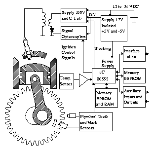
Our task was to develop a control unit for gas powered engines. For such engines, the main controlled parameter is ignition timing. We have designed the control unit for this task. It senses the position of the crankshaft by inductive sensing of a flywheel tooth gear and the start position mark. Except position, which is needed for the ignition angle setting and speed measurement, it can sense temperature of the engine, intake air pressure and additional auxiliary digital and analog inputs. A source of charge in a high voltage capacitor is also included in the unit as well as galvanically insulated coil control signals. Some auxiliary digital outputs are also provided for a gas arrangement control. A block diagram of our control unit is illustrated in Figure 2.
The unit is built on the basis of Philip's 80552 microcontroller with 32 kB of EPROM and the same capacity of RAM memory. The adjustment and constants are kept in 256 bytes of serial EEPROM memory. The unit is equipped with uLan communication interface, which can interconnect the unit with a laptop computer or another processor system. It is possible to adjust parameters from the connected computer at any time and changed values can be stored in EEPROM memory. Values read from sensors can be retrieved and processed in the computer. The communication can be used for downloading the new firmware and control maps into RAM memory for a period of one test run. Control maps can be modified on the fly.
As much as possible information about conditions/state of engine operation must be sensed for the tuning of the engine. It is not enough to know the actual engine state, but it is necessary to store parameters and engine state history courses to achieve the optimal adjustment. Basic information about speed, temperature and intake pressure is good for state probability analysis. The analysis can help to decide, which regions of operation states are more probable and are of higher interest for tuning. But this information does not represent sufficient information for computation and tuning of the engine efficiency. It is necessary to measure engine output power or torque and fuel consumption for such computations.
Because we wanted to tune the engine in regular on-road use, it was not possible to use diagnostic test bay. We decided to equip the engine with power measurement. There are two ways to achieve this. The first one is to measure torque and speed on the output shaft. The second one is to calculate energy gained in one piston stroke from the course and change volume of in-cylinder contents. We have decided to try the second possible way, because it could bring some more information usable for tuning. Volume of in-cylinder contents can be computed from the crankshaft position, but pressure must be measured by a high speed sensor with a good resistance to high temperature, vibrations and hot and aggressive gases.
There are more principles, which could be used for in-cylinder pressure measurement. Strain gauges are the most used sensors for pressure measurement in standard environment. But they are not suited for aggressive environment and high temperatures. High-tech technique utilizing changes of refraction index of optical fiber can be used for such experiments. But we are not equipped by instruments necessary for development of such gauge. Most commonly used sensors for rapidly changing pressure measurements are based on piezoelectric or piezoresistive principles.
Piezoresistive sensors have the advantage, that they are able to measure the absolute value of the pressure; on the other hand, they are more sensitive to temperature changes and are worse suited for high speed measurements. Second principle, piezoelectric sensors, have very short response time and high resistivity to high temperature. Their disadvantages are as follows: they generate very small charge or current response to the pressure; they cannot measure absolute pressure. Piezoelectric sensing has been selected according to the above mentioned facts.
Piezoelectric sensors can be manufactured from natural crystalic matters or artificial polycrystalic ceramics. The second ones are better for higher responses and possibility to produce demanded shape of the sensors. These sensors are commercially available, but the price of full sensing equipment is higher then $6,000 and the lifetime of such sensor is about 100 hours. It was too expensive for us. We decided to try to develop and produce such a sensor.
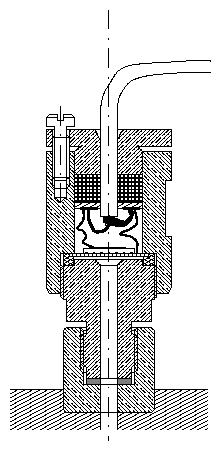
The final design of our sensor is drawn in Figure 3. Measurements are achieved by sagging of a steel membrane by pressure. A small piezoceramic disc with metalized sides is fastened onto the surface of the membrane and converts sagging to electric charge. An electrometric amplifier, which transfers charge to galvanically isolated voltage signal, has been constructed.
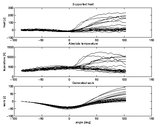
Firmware of our control unit has been enhanced to enable measurement and store course of the in-cylinder pressure along with the crankshaft position. Software is able to store 2048 samples with the maximal sampling rate of 4 kHz or store value after every crankshaft position counter change. Stored course can be uploaded by computer and gained energy of the corresponding thermodynamic cycles can be computed from the Equation 2. Not only energy can be computed, but also temperature course and heat transfers can be approximately computed if composition of mixture and intake pressure are known. It is possible by use another equations from section 2. Simplified equations for temperature and heat exchange are listed below:
| (5) |
| (6) |
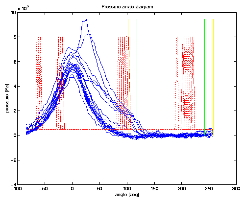
Computed approximate temperature and heat courses are brought in Figure 5.
Efficiency is determined by optimal composition of mixture and by exact timing of mixture injection, of ignition impulses and of the intake and exhaust valves. The ignition timing is the simplest adjustable parameter, because it needs no mechanical changes or adjustments. That is why, we have selected this variable as the best candidate for our experiments.
The basic relation between the gained energy from the cycle and ignition timing can be cleared by the next two situations. If the ignition is initiated too early, increasing pressure is pushing against the moving piston and a part of fuel energy is lost (even not only once, but twice). If the ignition is initiated too late, not all fuel is burnt before the exhaust valve is open, or a part of thermal energy and pressure is exhausted without profit.
It is necessary to define criteria and resolve their importance for finding the best adjustment of the engine control. Most considerable criteria are:
As has been shown before, it is possible to compute gained energy from in-cylinder pressure and volume courses. We have suggested a method, which enables to optimize engine control for the highest amount of gained energy for actual engine state. It can be achieved by approximate computation of supported heat course, which can be used for computation of gained energy from modified cycle. If we are able to estimate gained energy of the cycle with slightly modified ignition timing, we can decide, which direction of ignition timing modification can increase energy income. For most controllers, ignition timing dependence on the engine state (intake pressure, speed-RPM) is stored in the form of multidimensional table (map). Cell representing timing for engine state at the moment of pressure course measurement can be modified according to the previous computation.
We have designed a valuable control unit, which is produced by Magneton a. s., and is used for control of natural gas powered bus engines. The unit is equipped with additional functions, which can be used for tuning and storage of adjustment. The ability to read integral state parameters and pressure courses is also provided. These features has been used for gaining statistics of the probability of the engine working states. The unit is prepared for the automatic on-road tuning under control of connected laptop computer. The computer can use sophisticated software analysis of acquired data and tune the engine to find optimal adjustment. A method for optimization of ignition timing for each working state has been suggested and is in preparation for future experiments.
The presented project is a result of the team work and assistance of several people and that is why, I want to thank and give credit to my collaborators. The project is being headed by my tutor, Doc. Ing. Ondrej Vysoky CSc. He has invested a great amount of his time and work to this project. Some experiments have been tested on his own car, too. I want to thank to my father and PiKRON company which helped me with real manufacturing of both unit and a pressure sensor. Great credit also belongs to my work-colleague Petr Porazil for his help with the hardware design of the unit.