Go to: [Up |
Next (Scanning) |
Back |
Table of Contents]
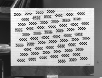
All five cameras were fully calibrated using a moving target with
indexed points of known position in 3-space. The target is mounted on
a rail with precise positioning device.
 The total of seven displacements of the target in the z-direction was
sufficient to recover perspective projection matrices and radial
distortion coefficients (k1) of all five cameras.
The mean calibration error was 0.17 ± 0.09 pixels in b/w cameras and
0.13 ± 0.08 pixels in the color camera. (The error is the magnitude
of difference between detected points of the calibration target and
the points projected using the recovered camera model and their true
3D coordinates).
The total of 60 views (one frame is four b/w images and one color
image) was acquired and processed. The entire field of view was
subdivided into four slightly overlapping segments. In each segment, a
landmark was affixed to the wall and used to register the individual
partial scans and the four partial reconstructions from different
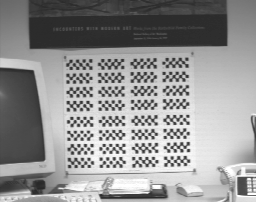
segments. All landmarks were identical and comprised 32 indexed points
that were located automatically. Below is a detailed view of landmark
A.
 Each of the four scene segments was further subdivided into several
slightly overlapping partial scan paths (8 in larger segments and 6 in
smaller segments). All paths start at the landmark and comprise two to
five sligtly overlapping frames each. The camera motion along the
partial scan path was calibrated with the help of a registration aid
that did not move during the camera view change. One frame before the
view change and one frame after the change provided two sets of aid's
points reconstructed in 3D space that were sufficient to recover the
Euclidean motion of the camera. We therefore did not rely on any prior
knowledge of the camera position which allowed us to move the cameras
freely around (each motion was limited in extent). A schematic
PostScript plan drawing is available.
The relative transformations among the four landmarks were recovered
in a similar way using several successive views of the registration
aid.
The difference between two successive calibrations was measured as
maximum Euler angles difference in rotation and as the magnitude of
the residual vector in translation as follows (all numbers should be
zero):
Between
landmarks | Rotation
[degrees] | Translation
[mm]
|
| A, B | 0.2 | 9.5
|
| A, C | 1 | 11
|
| C, D | 0.3 | 7
|
Go to: [Up |
Next (Scanning) |
Back |
Table of Contents]
]
Radim Sara
Last modified: Fri Nov 7 17:12:40 MET 1997


