Important notice, we are preparing to move development into SourceForge CVS. Please, look to http://sourceforge.net/projects/bdm/.
My personal page http://cmp.felk.cvut.cz/~pisa/ and this page http://cmp.felk.cvut.cz/~pisa/m683xx/bdm_driver.html continues to be updated to hold latest information about Linux m683xx BDM support. The copy of the page and its source will be probably moved into CVS and SourceForge as well.
BDM mode of the CPU32 halts execution of a normal machine code fetched from the memory and starts the internal MCU microcode to process commands received from a dedicated serial debug interface. These commands can be used to view and modify all CPU32 registers and to access into on-chip and external memory locations.
The CPU32 processor must be started in a special mode to enable BDM interface. This is achieved by holding the BKPT pin low during the reset time.
Switch to the BDM mode can be enforced by the following tree ways:
Motorola has defined a standard pinout for the debug connector, which is compatible with most of the development tools. Older versions have only eight pins and the newer ones add two additional pins for enforcing bus error and memory interface monitoring. Pins 2 to 10 of the new connector version are equivalent to the pins 1 to 8 of the older one.
|
Table 1 describes the function of these pins. Hardware dimensions of the connector are equivalent to the jumper array, which has 100 mils ( 2.54 mm ) spacing.
| Pin Number | Pin Name | Description |
| 1 | DS | Data strobe from target MCU.Not used in current interface circuitry |
| 2 | BERR | Bus error input to target. Allows development system to force bus error when target MCU accesses invalid memory |
| 3 | VSS | Ground reference from target |
| 4 | BKPT/DSCLK | Breakpoint input to target in normal mode;development serial clock in BDM.Must be held low on rising edge of reset to enable BDM |
| 5 | VSS | Ground reference from target |
| 6 | FREEZE | Freeze signal from target.High level indicates that target is in BDM |
| 7 | RESET | Reset signal to/from target.Must be held low to force hardware reset |
| 8 | IFETCH/DSI | Used to track instruction pipe in normal mode.Serial data input to target MCU in BDM |
| 9 | VCC | +5V supply from target.BDM interface circuit draws power from this supply and also monitors 'target powered/not powered' status |
| 10 | IPIPE/DSO | Tracks instruction pipe in normal mode.Serial data output from target MCU in BDM |
BDM uses 17 bit serial synchronous communication with the CPU32 processor. All data and command transfers are performed in an MSB first format. An internal CPU32 receiver is implemented by shift and latch registers. The CPU32 latches every input bit value on the DSI line at the time of rising edge detection of the DSCLK signal. Because of the DSCLK edge detection is performed synchronously with the system clock, the maximum DSCLK frequency is equal to one half of a system clock frequency. A 17 bit input word is latched after 17 rising edges on the DSCLK line then the CPU32 microcode sequencer is started to perform instruction or process extension words. Transmit latch register is updated by the CPU32 continuously. The transmit shift register and DSO pin reflect changes of the latch register until the first low level of 17 bit protocol is detected on the DSCLK line. Then the state of the DSO line can be read as a MSB received bit. Then the transmit shift register is not updated by the transmit latch register until all 17 bits are read. The DSO line is changed only after rising edges of the DSCLK line during the rest of transfer.
|
Command and data transfers initiated by the development system should clear bit 16. The current implementation ignores this bit; however, Motorola reserves the right to use this bit for future enhancements. The CPU32 returns 17 bit status or value every time 17 bits are send to it. The meaning of 17 bit status is described in Table 2. Some commands except the first command word need an additional address and data words. Figure 2 shows the general BDM instruction format without 16-th bit.
| Bit 16 | Data | Message Type |
| 0 | xxxx | Valid Data Transfer |
| 0 | FFFF | Command Complete; Status OK |
| 1 | 0000 | Not Ready with Response; Come Again |
| 1 | 0001 | BERR Terminated Bus Cycle; Data Invalid |
| 1 | FFFF | Illegal Command |
Table 3 contains possible BDM commands for the CPU32 processors family. I have noticed, that the new ColdFire family processors use same basic command set with additional real-time commands. Changed RSREG and WSREG commands need to address more registers and that is why an additional register address word is necessary for these instructions. Another big change can be seen with ColdFire BDM cable, because of the ColdFire has single-stepping flip-flop built inside.
| Command | Mnemonic | Code | Additional Words and Notices |
| Read D/A Register | RREG | 218r | receive two words with value from CPU32 |
| Write D/A Register | WREG | 208r | send two words with value to CPU32 |
| Read System Register | RSREG | 258s | receive two words with value from CPU32 |
| Write System Register | WSREG | 248s | send two words with value to CPU32 |
| Read Memory Location | READ | 19tt | send 2 word address and receive 1 or 2 words value |
| Write Memory Location | WRITE | 18tt | send 2 word address and 1 or 2 words value |
| Dump Memory Block | DUMP | 1Dtt | receive 1 or 2 words value from next memory locationto location selected by previous READ command |
| Fill Memory Block | FILL | 1Ctt | send 1 or 2 words value for next memory locationto location selected by previous WRITE command |
| Resume Execution | GO | 0C00 | Pipe is re-filed from RPC location |
| Patch User Code | CALL | 0800 | Current program counter is stacked at the locationof the current stack pointer and two additional wordsdefine subroutine start address |
| Reset Peripherals RST Asserts | RST | 0400 | Asserts RESET for 512 clock cycles,but the CPU is not reset by this command |
| No Operation | NOP | 0000 | NOP performs no operation and may beused as a null command |
Table 4 describes the meanings of the last variable nibble or byte values in command codes.
| Symbol | Value | Mnemonic | Meaning |
| r | 0 to 7 | D0 to D7 | Data Register |
| 8 to F | A0 to A7 | Address Register | |
| s | 0 | RPC | Return Program Counter |
| points where execution will continue | |||
| 1 | PCC | Current Instruction Program Counter | |
| points to first byte of last executed instruction | |||
| it contains 00000001 when double bus fault | |||
| appears immediately after reset | |||
| 8 | ATEMP | Temporary Register A | |
| 9 | FAR | Fault Address Register | |
| A | VBR | Vector Base Register | |
| B | SR | Status Register | |
| C | USP | User Stack Pointer | |
| D | SSP | Supervisor Stack Pointer | |
| E | SFC | Source alternate function type of bus cycle | |
| MOVES instruction and BDM memory transfers | |||
| F | DFC | Destination alternate function of bus cycle | |
| MOVES instruction and BDM memory transfers | |||
| tt | 00 | BYTE | 8 bit data in least significant byte of one word |
| 40 | WORD | 16 bit data transferred in one word | |
| 80 | LONG | 32 bit data transferred in two words |
There exist two standard wirings of a cable between the CPU32 BDM interface and standard PC printer port. The first is public domain interface ( PD_BDM ). It was published by Motorola ( its support BBS ) and can be used with free BD32 ( bd32v122.zip ) debugger and BDM library example implementation ( bdm-v090.zip ). Both are writted by Scott Howard. The second cable is provided with Motorola commercial systems and is known as ICD_BDM cable. This cable can be used with both above mentioned programs and with the free TPU debugger and downloader ( tpubug.zip ).
The schematic diagram of one of possible PD cable implementations is in figure 3. It is a simple implementation with 8 pin cable only, but it works for me without serious problems with 1 m cable from PC and 20 cm cable to MC68332.
|
The cable compatible with Motorola ICD32 system can be seen in figure 4. I have seen an original schematic for ICD32 cable, but I do not have this cable, so GAL16V8 function is only my own solution. In my experience, it works with all free software I have ( Linux BDM driver, DB32, BDM library and TPU debugger ). I am not sure about legal state of this cable, but it can be used with free Motorola software and free source for BDM library describes its function, so it should be free. This cable works better than the previous one for the following three reasons:
|
GNU debugger is used in many native and cross development tool-chains in UNIX type environment. It is a very powerfull debugger controlled from its command line. There exist many interactive menu-driven and mouse-driven user interfaces for this debugger, too ( for example GDBTk, DDD, Rhide and XXGDB ). This debugger is very well suited for the cross-development for 32 bit embedded targets. It recognize most of the Motorola MCUs with CPU32 and ColdFire processor cores. These targets may be connected by the serial line using Motorola board ROM monitor or special protocols for some operating systems ( for example VxWorks ). Such target debugging can be achieved by the GDB remote target debugging by any usual serial stream connection ( RS-232 or TCP/IP connection ).
To use BDM interface by GDB, two problems must be solved. First, it is not good practice to directly manipulate by ports under UNIX systems. It means that the kernel mode BDM driver should be written to implement the BDM character device. Such device can accept and perform regular read/write system calls and for special action ( for example single step ) use IOCTL interface. The second part must be done to enable GDB to understand and send BDM commands by read/write interface to the BDM driver and controll target state through the driver IOCTL interface.
In future, such two layer implementation can be usefull for GDB independence on the host system, because only the BDM driver will be host specific. Recently, this driver exists for Linux operating system. Patch files for GDB versions 4.16 till GDB-5.1.1 exist to use this driver. The authors of the BDM driver and GDB target interface are stated bellow
Gunter Magin started to develop new version of the ICD compatible cable with ispGAL22V8, but it is not finished. Patches for GDB-5.1.1 are compatible with standard GAL16V8 cable as well.
The latest version of the patches for gdb-5.1.1 based on Magin's and my code is stored in archive gdb-5.1.1-bdm-patches-pi1.tar.gz. This version contains all my changes for support of the Linux kernels 2.2.x and 2.4.x, faster and better timing ( at least I hope so ) and flash programming support. This version can be found in the archive. There is an initial version of the ispGAL22V8 based EFICD, as well.
To start debugging session, next things must be set-up correctly. The board with one of the Motorola MC683xx processors must be connected to a PC printer port by one of debugging cables mentioned above ( ICD32 or PD cable ). The BDM driver must be compiled for a correct Linux kernel version ( provided driver sources should work with 2.2.xx and 2.4.xx kernels, version for gdb-5.1.1 was tested with 2.4.7 kernel ). The sources of BDM driver can be found in ``gdb-5.1.1-bdm-patches-pi1.tar.gz''. Next commands can be used to compile driver.
tar -xzf gdb-5.1.1.tar.gz
cd gdb-5.1.1-bdm-patches/bdm_driver
make
INTERFACE+= -D ICD_INTERFACE
AUTOLOADING=-DMODVERSIONS
#BDM_DEFS += -D BDM_TRY_RESYNCHRO
#CFLAGS+= -D__SMP__
The compiled BDM driver ``bdm.o'' should placed to ``/lib/modules/kernel_version/misc'' directory. The driver must be inserted into the kernel when modules are used ( # insmod bdm ). When kernel autoloading of missing modules is used ( kmd or kerneld ), next line can be inserted into file ``/etc/modules.conf''.
Special character files must be created. Standard names for above described cables and driver sources are pd_bdm0, 1, 2 and icd_bdm0, 1, 2 ( special files can be created by provided MAKEDEV script ). Ending numbers of special files select used printer port base address ( 0..378h, 1..278h, 2..0x3BCh ). Special files select between public domain ( pd_bdmx ) and ICD32 cable ( icd_bdmx ). In most cases, only one target processor is used, so it is a good practice to make symbolic link bdm to the used interface special file ( for example ln -s /dev/pd_bdm0 /dev/bdm ).
Patched version of the GDB must be compiled. Next command sequence can be used to prepare and compile the GDB.
tar -xzf gdb-5.1.1.tar.gz
patch -p <gdb-5.1.1-bdm-patches-pi1/gdb-5.1.1-bdm.patch-1
cd gdb-5.1.1
./configure --target=m68k-bdm-coff
--enable-targets=m68k-linux-elf,m68k-coff,m68k-a.out-linux
make
make intall
The compiled GDB executable must be start and the target must be connected. Setting up of the BDM interface can be prepared as a GDB script or automatic initialization script. For the target without on-board memory setup code, chipselects and system integration module ( SIM ) must be initialized ( from gdb .init script or .bdmmb file ). A step by step manual initialization from GDB prompt is shown in the next example
set remotecache off
bdm_timetocomeup 600000
bdm_autoreset off
bdm_setdelay 70
bdm_reset
set $sfc=5
set $dfc=5
The latest versions of BDM driver has support for bdm_setdelay 0, which enables fast mode with automatic waiting for target memory access finish. This mode should not be used for initial SIM module settings for targets without on-board setup code or other targets, where direct GDB initiated freeze is used immediately after reset ( bdm_timetocomeup 0 ), because target clock oscillator and PLL multiplier can be unstable at that time. Delay can be set to zero after SIM setup.
If you have compiled target memory image with debug information ( for example RTEMS system absolute COFF or ELF image ) you can start it by the following commands.
break main
run
Next paragraphs give expanded description of GDB initialization and first steps with BDM. It is mentioned for user with troubles and is based on my mail exchange with them.
Start GDB first. If it is compiled and installed right, GDB can be started from shell prompt by command ``m68k-bdm-coff-gdb''. Check, that BDM target is compiled in. List of included GDB targets is obtained by typing ``help target'' after GDB prompt ``(gdb)''. Result is something like next output for GDB configured for m68k-bdm-coff
target bdm -- Debug with the Background Debug Mode
target cpu32bug -- Debug via the CPU32Bug monitor
target exec -- Use an executable file as a target
target extended-remote -- Use a remote computer via a serial line
target remote -- Use a remote computer via a serial line
bdm_autoreset bdm_entry bdm_release bdm_status bdm_checkcable bdm_init
bdm_reset bdm_timetocomeup bdm_debug_driver bdm_log bdm_setdelay
(gdb) bdm_
You need to insert the BDM driver module into the Linux kernel to open connection to BDM target. Section 5 explains that. Some message should be seen in ``/var/admsyslog''. There may be problems, when BDM and printer drivers compete for same parallel port. Removing of ``lp'' module by ``modprobe -r lp parport_pc'' should help in such case.
Next step is to connect GDB to the target board. You need the cable ( PD or ICD ) and 6833x ( CPU32 ) board. I suggest to connect RS232 cable to board and PC first, then connect BDM cable. It protects BDM pins and PC printer port against damage (at least CPU32 BDM pins are very sensitive to overvoltage). You can type "target bdm /dev/bdm" ( it expects link /dev/bdm pointing to used icd_bdm? or pd_bdm? device as suggested above ). You should set speed of BDM communication by "bdm_setdelay 75" or more for beginning. If you have no problems later, you can set little delay. ( I can use fast mode with delay 0 on my Duron 600MHz ZX7 mainboard with onboard PP and on some more 686, 586 and 486 configurations with above described ICD compatible cable. ) If your 6833x board has onboard EPROM with initialization of chipselects, you can set "bdm_timetocomeup 600000" or to what necessary for initialize. If there is no onboard initialization then "bdm_timetocomeup 0" will be reasonable. "bdm_reset" should be entered for safety. You should be able to read accessible memory after that by "x /100lx 0x1234" command. If range is accessible and EPROM is mapped there, you should see its contents. If RAM is in tested range, you can try "p *(int*)0x1234=0xAA55BB66" then "x /lx 0x1234" should confirm that value was stored and read again. If range is not mapped to some internal chipselect and external circuitry does not acknowledge access, message "Error accessing memory address 0x1234 : Unknown error 616" or similar should appear. You need not to have loaded any program for this test.
Driver and BDM library ( part of GDB ) have full logging facilities for finding of problems with both software and hardware. Two logging commands can be entered at GDB prompt. The first one is "bdm_log {onoff}". Most of GDB-BDM driver activity is logged into file "bdm-dbg.log" in current directory, when "bdm_log" is on. Second command "bdm_debug_driver level" is designed for control of the kernel BDM driver logging. Level 0 mean no logging, 1 basic logging and 2 log all driver activity. Driver logging messages are processed by klogd and syslogd and in most cases appears in the "/var/log/syslog" file.
Command for GDB and BDM initialization can be stored into file. You can invoke interpretation of this file by "source <filename>" from GDB prompt. If script is stored under name ".gdbinit68" ( or ".gdbinit" - depends on configuration of GDB ) in current directory, then it is invoked at every GDB start.
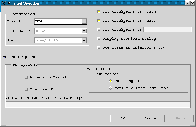
The insight graphical frontend to GDB can be build for BDM target same way as plain GDB. New BDM target must be added to file targetselection.itb. See file insight-5.1-target.patch. Link from /dev/bdm to right interface must be set for working of BDM target selection. Right method for connecting to target is to use RUN as shown in the picture 5.
|
You should read this section, if you have 68332 board without onboard chipselect initialization. It can be useful to read next if you want to program your own CPU32 initialization in ``C'' source code. I expect, that everybody seriously interested in 68332 have downloaded PDF or printed copy of [2] and [3]. Examples are written such way, as they can be used in GDB script file or typed after GDB prompt. Another way will be described later at end of this section.
Essential system control registers must be initialized first. The first line in every example is register address and its name. The second and third line contains definition of bitfields in register. Next is used value in binary notation and last is GDB syntax.
# 15 14 13 12 11 10 9..8 7 6 5 4 3 0
# EXOFF FRZSW FRZBM 0 SLVEN 0 SHEN SUPV MM 0 0 IARB
# 0 0 0 0 DATA11 0 0 0 1 1 0 0 1 1 1 1
set *(short *)0xfffa00=0x42cf
# 7 6 5.4 3 2 1 0
# SWE SWP SWT HME BME BMT
# 1 MODCLK 0 0 0 0 0 0
set *(char *)0xfffa21=0x06
# write 0x55 0xAA for watchdog
# 15 14 13........8 7 6 5 4 3 2 1 0
# W X Y EDIV 0 0 SLIMP SLOCK RSTEN STSIM STEXT
# 0 0 1 1 1 1 1 1 0 0 0 U U 0 0 0
set *(short *)0xfffa04=0x7f00
# 15 14 13.12 11.10 9.8 7.6 5.4 3.2 1.0
# 0 0 CSPA0[6] CSPA0[5] CSPA0[4] CSPA0[3] CSPA0[2] CSPA0[1] CSBOOT
# 0 0 DATA2 1 DATA2 1 DATA2 1 DATA1 1 DATA1 1 DATA1 1 1 DATA0
# CS5 CS4 CS3 CS2 CS1 CS0 CSBOOT
# FC2 PC2 FC1 PC1 FC0 PC0 BGACK BG BR
#
# 00 Discrete Output
# 01 Alternate Function
# 10 Chip Select (8-Bit Port)
# 11 Chip Select (16-Bit Port)
#
set *(short *)0xfffa44=0x3fff
# 0xFFFA46 - CSPAR1 - Chip Select Pin Assignment Register 1
# 15 14 13 12 11 10 9.8 7.6 5.4 3.2 1.0
# 0 0 0 0 0 0 CSPA1[4] CSPA1[3] CSPA1[2] CSPA1[1] CSPA1[0]
# 0 0 0 0 0 0 DATA7 1 DATA76 1 DATA75 1 DATA74 1 DATA73 1
# CS10 CS 9 CS8 CS7 CS6
# A23 ECLK A22 PC6 A21 PC5 A20 PC4 A19 PC3
#
set *(short *)0xfffa46=0x03ff
# Chip selects configuration
#
# 0xFFFA48 - CSBARBT - Chip-Select Base Address Register Boot ROM
# 0xFFFA4C..0xFFFA74 - CSBAR[10:0] - Chip-Select Base Address Registers
# 15 14 13 12 11 10 9 8 7 6 5 4 3 2 0
# A23 A22 A21 A20 A19 A18 A17 A16 A15 A14 A13 A12 A11 BLKSZ
# reset 0x0003 for CSBARBT and 0x0000 for CSBAR[10:0]
#
# BLKSZ Size Address Lines Compared
# 000 2k ADDR[23:11]
# 001 8k ADDR[23:13]
# 010 16k ADDR[23:14]
# 011 64k ADDR[23:16]
# 100 128k ADDR[23:17]
# 101 256k ADDR[23:18]
# 110 512k ADDR[23:19]
# 111 1M ADDR[23:20]
#
#
# 0xFFFA4A - CSORBT - Chip-Select Option Register Boot ROM
# 0xFFFA4E..0xFFFA76 - CSOR[10:0] - Chip-Select Option Registers
# 15 14 13 12 11 10 9 6 5 4 3 1 0
# MODE BYTE R/W STRB DSACK SPACE IPL AVEC
# 0 1 1 1 1 0 1 1 0 1 1 1 0 0 0 0 - for CSORBT
#
# BYTE 00 Disable, 01 Lower Byte, 10 Upper Byte, 11 Both Bytes
# R/W 00 Reserved,01 Read Only, 10 Write Only, 11 Read/Write
# SPACE 00 CPU, 01 User, 10 Supervisor, 11 Supervisor/User
#
set *(long *)0xfffa48=0x0e0468b0
# BOOT ROM 0x0e0000 128k RO UL
set *(long *)0xfffa4c=0x0003503e
# CS0 RAM 0x000000 64k WR U
set *(long *)0xfffa50=0x0003303e
# CS1 RAM 0x000000 64k WR L
set *(long *)0xfffa54=0x0003683e
# CS2 RAM 0x000000 64k RO UL
set *(long *)0xfffa58=0x02036870
# CS3 RAM 0x020000 64k RO UL
set *(long *)0xfffa5C=0xfff8680f
# CS4
set *(long *)0xfffa60=0xffe8783f
# CS5
set *(long *)0xfffa64=0x02033030
# CS6 RAM 0x020000 64k WR L
set *(long *)0xfffa68=0x02035030
# CS7 RAM 0x020000 64k WR U
set *(long *)0xfffa6c=0x01036870
# CS8 RAM 0x010000 64k RO UL
set *(long *)0xfffa70=0x01033030
# CS9 RAM 0x010000 64k WR L
set *(long *)0xfffa74=0x01035030
# CS10 RAM 0x010000 64k WR U
The meaning of the nums depends on the command letter:
write to address (num1) contents (num2) length is (num3) bytes. Only 1, 2, 4 bytes are permitted.
fill memory area beginning at (num1) with byte value (num2) length (num3) bytes.
copy memory area from (num1) to (num2) with length (num3) bytes.
This utility is mainly designed for programming of FLASH memories mapped in address space of CPU32. It can be used for fast and simple loading and starting programs in RAM too. Original authors are G. Magin and D. Jeff Dionne. There is presented rewritten preliminary version by Pavel Pisa. The new version can program more than one FLASH memory mapped in address space and is able to autodetect type of memory and can take start address of FLASH regions from 683xx chipselect registers.
Utility uses the BFD object files management library and can load any format configured into the BFD library (iHEX, S-record, coff-m68k, elf-m68k etc.). The current version uses recent version of "bdmlib" library and it will be possible to integrate flash functions directly into GDB.
Next packages and files are needed to compile and install "bdm-load":
The "bdm-load" accepts command line parameters. If there is no error in parsing of the parameters it processes requested actions and switches into interactive mode. Switching into interactive mode can be suppressed by the "-script" parameter. Description of command line interface follows.
-h --help - this help information!
-i --init-file=FILE - object file to initialize processor
-r --reset - reset target CPU before other operations
-c --check - check flash setup (needed for auto)
-e --erase - erase flash
-b --blankck - verify erase of flash
-l --load - download listed filenames
-g --go - run target CPU from entry address
-s --script - do actions and return
-d --bdm-delay=d - sets BDM driver speed/delay
-f --flash=TYPE@ADR - select flash
Possible commands in interactive mode :
There can be found more different types of BDM interfaces on many of Motorola MCUs except the CPU32 BDM described above.
The HC12 family of microcontrollers uses the one wire open collector BDM interface. It has very curious timing which enables bidirectional asynchronous bit transfer over one wire. It can be connected to RS-232 port through simple converter. BDM mode instruction are not executed by special HC12 microcode, but program counter of the regular HC12 CPU is vectored into special on chip ROM code.
The HC16 uses the BDM interface more similar to CPU32 one.
ColdFire MCUs have BDM mode implemented similar way as CPU32. The BDM cable is simplified, because of the single-step flip-flop and some logic are integrated directly into ColdFire MCUs. BDM command set is enhanced with real time monitoring functions. These functions and target memory access can be performed in parallel to running ColdFire CPU.
PowerPC MCUs have BDM interface too. I lack more information about it.
The BDM drivers and cables combinations available for GDB and Linux operating system are summarized in table 5.
| Cable | MCU Type | ||
| CPU32(6833x) | CPU32+(68360) | ColdFire | |
| PD ( public Domain ) | Gunter's driver [1][11] | Eric's driver [12] | - |
| ICD32 ( P&E ) | Gunter's driver [1][11] | * | - |
| ColdFire ICD | - | - | Eric's driver [12] |
Port of BDM driver for Window NT can be found on page [14].
The BDM resources for PowerPC based Motorola microcontrollers (MPC5xx/MPC8xx) could be found at pages of bdm4gdb project [15].