

Next: Representation with recorded images
Up: Plenoptic modeling and rendering
Previous: Plenoptic modeling and rendering
Contents
The original 4D lightfield [99] data structure employs a two-plane parameterization. Each light ray passes through two parallel planes with plane coordinates  and
and  (see Figure 8.8).
Figure 8.8:
4D representation of viewing rays in the regular grid representation of the lightfield.
 |
Thus the ray is uniquely described by the 4-tuple  . The
. The  -plane is the viewpoint plane in which all camera focal points are placed on regular grid points. The cameras are constructed such, that the
  -plane is their common image plane and that their optical axes are perpendicular to it. From the two-plane parameterization new views can be rendered by placing a virtual camera on an arbitrary viewing position with arbitrary parameters (e.g. focal length) and intersecting each viewing ray with the two planes at
  . The resulting radiance is a look-up into the regular grid. For rays passing in between the
  and
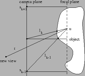
and  grid coordinates an interpolation is applied that will degrade the rendering quality depending on the scene geometry. In fact, the lightfield contains an implicit geometrical assumption: The scene geometry is planar and coincides with the focal plane (Figure 8.9). Deviation of the scene geometry from the focal plane causes image warping. Figure 8.9 shows that the radiance of the viewing ray
  is interpolated from radiance values
  and
and  of neighboring camera viewpoints, depending on the geometrical deviation from the focal plane.
Figure 8.9:
Viewpoint interpolation between  and
and  .
.
 |
Linear interpolation between the viewpoints in  and
and  introduces a blurred image with ghosting artifacts. In reality we will always have to choose between high density of stored viewing rays with high data volume and high fidelity, or low density with poor image quality.
If we have a sequence of images taken with a hand-held camera, in general the camera positions are not placed at the grid points of the viewpoint plane. In [54] a method is shown for resampling this regular two plane parameterization from real images recorded from arbitrary positions (rebinning). The required regular structure is resampled and gaps are filled by applying a multi-resolution approach, considering depth corrections. The disadvantage of this rebinning step is that the interpolated regular structure already contains inconsistencies and ghosting artifacts because of errors in the scantily approximated geometry. To render views a depth corrected look-up is performed. During this step the effect of ghosting artifacts is repeated so duplicate ghosting effects occur.


Next: Representation with recorded images
Up: Plenoptic modeling and rendering
Previous: Plenoptic modeling and rendering
Contents
Marc Pollefeys
2000-07-12

![]() and
and ![]() introduces a blurred image with ghosting artifacts. In reality we will always have to choose between high density of stored viewing rays with high data volume and high fidelity, or low density with poor image quality.
introduces a blurred image with ghosting artifacts. In reality we will always have to choose between high density of stored viewing rays with high data volume and high fidelity, or low density with poor image quality.