

Next: conclusion
Up: Plenoptic model
Previous: Refinement
Contents
Figure 8.11:
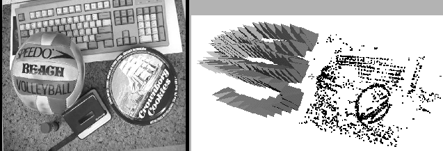
Image of the desk sequence (left) and result of calibration step (right). The cameras are represented by little pyramids.
 |
Figure 8.12:
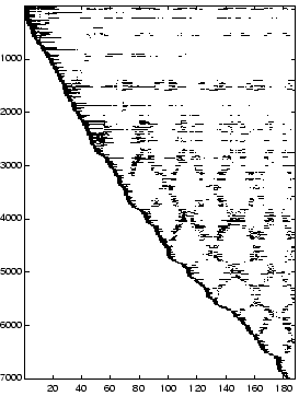
Tracking of the points over the sequence. Points (vertical) versus images (horizontal).
 |
We have tested our approaches with an uncalibrated sequence of 187 images showing an office scene. Figure 8.11 (left) shows one particular image. A digital consumer video camera was swept freely over a cluttered scene on a desk, covering a viewing surface of about  . Figure 8.11 (right) shows the calibration result.
Figure 8.12 illustrates the success of the modified structure and motion algorithm as described in Section 5.3. Features that are lost are picked up again when they reappear in the images. Figure 8.13 (left) shows the calibration results with the viewpoint mesh.
One result of a reconstructed view is shown in Figure 8.13 (right).
Figure 8.13:
Calibration result and viewpoint mesh(left) and reconstructed scene view using one plane per image triple.
 |
Figure 8.14 shows details for the different methods. In the case of one global plane (left image), the reconstruction is sharp where the approximating plane intersects the actual scene geometry. The reconstruction is blurred where the scene geometry diverges from this plane. In the case of local planes (middle image), at the corners of the triangles, the reconstruction is almost sharp, because there the scene geometry is considered directly. Within a triangle, ghosting artifacts occur where the scene geometry diverges from the particular local plane. If these triangles are subdivided (right image) these artifacts are reduced further.
Figure 8.14:
Details of rendered images showing the differences between the approaches: one global plane of geometry (left), one local plane for each image triple (middle) and refinement of local planes (right).
 |


Next: conclusion
Up: Plenoptic model
Previous: Refinement
Contents
Marc Pollefeys
2000-07-12


![]() . Figure 8.11 (right) shows the calibration result.
Figure 8.12 illustrates the success of the modified structure and motion algorithm as described in Section 5.3. Features that are lost are picked up again when they reappear in the images. Figure 8.13 (left) shows the calibration results with the viewpoint mesh.
One result of a reconstructed view is shown in Figure 8.13 (right).
. Figure 8.11 (right) shows the calibration result.
Figure 8.12 illustrates the success of the modified structure and motion algorithm as described in Section 5.3. Features that are lost are picked up again when they reappear in the images. Figure 8.13 (left) shows the calibration results with the viewpoint mesh.
One result of a reconstructed view is shown in Figure 8.13 (right).

