

Next: Augmented Video
Up: Augmented reality
Previous: Overview
Contents
The structure and motion recovery approach described in this text can easily be adapted to fit the needs of AR applications. However, the methods of Chapter 4 and 5 implicitly assume that two consecutive views are not 'too close'.
If this is the case, e.g.
for two consecutive images in a video sequence, the computation of the
matrix F and therefore the determination of the corner
matches between the two images becomes an ill-conditioned problem.
Even if the matches could be found exactly the updating of
motion and structure is ill-conditioned as the triangulation of newly
reconstructed 3D points is very inaccurate as depicted in
Figure 8.15.
Figure 8.15:
If the images are chosen too close to each other the position and orientation of the camera hasn't changed much. Uncertainties in the image corners lead to a large uncertainty ellipsoid around the reconstructed point (left). If images are taken further apart the camera position and orientation may differ more from one image to the next, leading to smaller uncertainty on the position of the reconstructed point (right).
 |
We solved this problem by running through the video sequence a first
time to build up an accurate but crude 3D reconstruction of the real
environment. Accuracy is obtained by using key-frames which are
separated sufficiently from each other in the video sequence (see
Figure 8.16). Structure and motion are extracted for
these key-frames. In the next step each unprocessed image is calibrated
using corner matches with the two key-frames between which it is
positioned in the video sequence. For these new images no new 3D
structure points are reconstructed as they will probably be
ill-conditioned due to the closeness of the new image under scrutiny
and its neighboring key-frames. In this way a crude but accurate
3D structure is built up in a first pass along with the calibration of
the key-frames. In a second pass, every other image is calibrated using
the 2D-3D corner matches it has with its neighboring key-frames. This
leads to both a robust determination of the reconstructed
3D environment and the calibration of each image within the video
sequence.
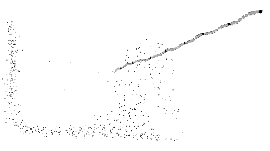
Figure 8.16:
The small dots on the background represent the recovered crude 3D environment. The larger dark spots represent camera positions of key-frames in the video stream. The lighter spots represent the camera positions of the remaining frames.
 |


Next: Augmented Video
Up: Augmented reality
Previous: Overview
Contents
Marc Pollefeys
2000-07-12


